


YAGEO Group is excited to introduce our latest technology in coupled inductors. Our expansion of inductors powers processors, memory, FPGAs, and ASICs in servers, data centers, and storage systems. These newest product developments are specifically designed for coupled inductors and leverage our existing high-volume automated manufacturing to ensure quality, reliability, and cost-effectiveness. Devices are offered exclusively with voltage regulators employing power-regulating devices manufactured by ADI/Maxim.
Traditionally, these applications have used single winding inductors in a multiphase buck topology, which allows currents to be distributed through parallel ‘paths’ or phases. By operating each phase staggered, the ripple currents in each phase tend to cancel at the output, and the overall ripple current seen at the load is much smaller than the ripple in each phase. This approach allows smaller inductances to be used (typically on the order of 50-300nH). It can enable design engineers to trade off how quickly the converter responds to a change in the load current (transient response) versus the stability of the control loop. By adjusting the number of phases used in the converter, the designer can optimize the circuit for their specific application.
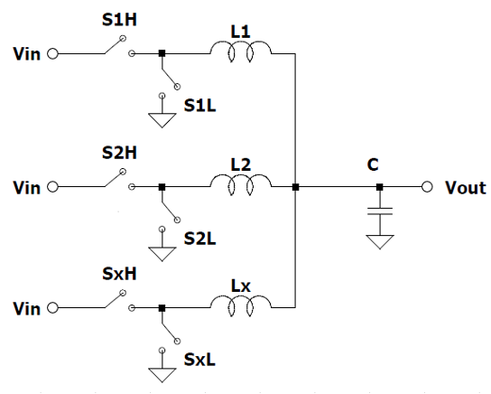
As shown previously, the uncoupled multiphase does an excellent job in addressing the challenges of supplying power for computing applications. The contradictory requirements of both maintaining a minimum output voltage ripple (proportional to diout) and allowing for the use of a smaller inductance per phase to enable fast transient response are all addressed. However, as the inductance per phase in the uncoupled multiphase buck is reduced, the ripple current (di) per phase increases. This, in turn, increases the peak current per phase, the switching losses and the I2R losses, which affect the overall efficiency of the power supply. The goal then is to find a circuit that will enable lower phase ripple while not sacrificing transient response.
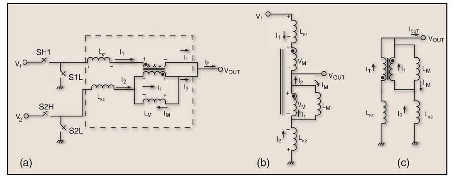
The coupled inductor approach is similar to the uncoupled version, but instead of using discrete inductors per phase, the inductors are combined on a single core structure. The simplest way to envision a coupled inductor is to consider it a multi-winding transformer. The standard approach to modeling a transformer is to use an ideal transformer — one that has no losses, perfect coupling and converts voltage and current as a ratio of the turns of each winding, N / N2 — and to assign a magnetizing inductance (LM) to one of the windings, which represents the loss associated with the magnetizing current, and a leakage inductance (LK) to each winding, which represents the loss as a result of imperfect coupling inductor, each winding will have the same turns (N1 =N2 =Nx ); therefore, the voltage and currents on each winding of the ideal transformer will be equal. The magnetizing inductance (LM) and the sum of the leakage inductances (LK) can be calculated and measured, providing a good basis for the analysis.
Although the coupling ratio does not affect the output ripple, it significantly affects the phase current ripple. It is apparent from this analysis that the uncoupled multiphase buck allows for reduced output ripple when compared to the single-phase buck. Conversely, if lower inductance values are used, it can provide the same output ripple with a faster transient response. The penalty in the uncoupled multiphase buck is the increased ripple per phase and associated losses. The coupled multiphase buck solves this by allowing for reduced phase ripple for the same output ripple, or conversely, if lower values of leakage inductance are used, one can achieve an even faster transient response without increasing the phase ripple.
The PGL725XHLT comes in 6mm max height, with an inductance of 35nH and saturation currents of 100A+/73A+ @105. This series has 2, and 3 phase parts, which would be used widely for the Vcore power with strict height requirements.
Damon Huang | Product Marketing, Specialized Power PBU, YAGEO Group
The PGL725XHLT has a max height of 6 mm, an inductance of 35nH, and saturation currents of 100A+/73A+ @105. This series has two- and three-phase parts, which would be widely used for Vcore power with strict height requirements.
To view, compare and download data sheets for our Power Bead Inductor Series utilize our Product Finder and simply enter the prefix of the part number. To inquire about lead times, competitive pricing, samples and more, just contact us or use our quote form accessed using the button below.